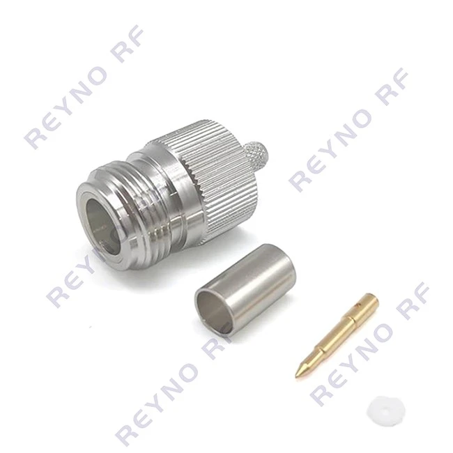
The core objective of crimping specifications for female terminals is to ensure the reliability of the electrical connection and mechanical strength, primarily achieved by controlling crimp height, width, and cross-sectional quality.
Crimping Dimension Specifications
Dimensional standards for terminal crimping are typically provided by the manufacturer; requirements vary based on terminal series and material. The key control parameters are crimp height and width.
Crimp Height: This is the most critical parameter and requires precise measurement using a micrometer. For example, for 0.5–1.0 mm² wires, the crimp height typically ranges from 1.2 mm to 1.6 mm. Manufacturer specifications must be strictly followed; excessive height results in a loose crimp and poor conductivity, while insufficient height can sever copper strands and compromise mechanical strength.
Crimp Width: This is usually linked to crimp height; provided the crimp height meets specifications, the width generally falls within the required range automatically.
Conductor Brush (visible copper strands at the front) and Insulation Crimp: The conductor brush typically requires an extension of 0.5 mm–1.5 mm. The insulation crimp zone must tightly wrap the insulation without damaging or severing the copper strands.
Cross-Sectional Inspection Requirements
In sectors requiring high reliability (such as automotive and aerospace), crimp cross-section analysis is mandatory; it serves as the gold standard for verifying crimp quality.
Characteristics of a Compliant Cross-Section: All copper strands are deformed into irregular polygons without fracturing; there are no excessive voids; the terminal material wraps tightly; and a proper "bell-mouth" exists at the bottom to prevent stress concentrations from severing the wire strands.
Common Non-Compliant Types: These include excessive crimp height (excessive voids), insufficient crimp height (severed copper strands), missing or oversized bell-mouths, and insulation pressed into the conductor crimp zone.
Tooling and Process Specifications
Crimping Dies: Specialized crimping dies that perfectly match the terminal brand and specifications must be used. Mixing terminals and dies from different brands can lead to crimping failure.
Crimping Machine:** Crimping force must be calibrated regularly to ensure consistent and stable crimping operations.
Pull-out Force Test: Regular pull-out force testing is required to verify mechanical strength. For example, the pull-out force for a 1.0 mm² wire after crimping typically needs to exceed 150 N (specific values are subject to industry standards, such as QC/T 29106, or manufacturer specifications).
Safety and Material Specifications
Prohibited Crimping: It is strictly forbidden to crimp two wires into a single female terminal.
Wire Matching: The terminal must match the wire's cross-sectional area; do not crimp a thick wire into a small terminal or a thin wire into a large terminal.
Terminal Material: Common materials include tin-plated brass or phosphor bronze; gold-plated terminals are required for high-demand environmental conditions to prevent oxidation.